Exhaust Shields

6/22/01 Heat Shields: Step by Step
Last week I successfully made one heat shield for my exhaust manifold, but didn’t take too many pictures of the process. This week, I stopped every so often to photograph the steps as I made the second heat shield. My apologies if this seems like a repeat of last week, but some people may find interest in ALL the gory details!

The first step was to trace the template out on the 1100 series aluminum, leaving enough aluminum on the edges to fold over. Depending how good you are at using tin snips, file the edges of the aluminum to remove all the burrs. For the areas that will have tight curves, leave some extra material in case the metal begins to stress crack. You can save the piece by catching the crack early, filing the crack away, and annealing the area to help stretch it some more.

After getting smooth edges all around the sheet, I annealed the aluminum and clamped it in the wood buck.

I made a special smaller buck to work specifically on the tight radius curves. This buck allowed me easier maneuverability when positioning in this area. As I tapped with a round tool in this area, I could feel the aluminum “work harden” and bend less with each blow. Before it would start to crack, I removed the clamps, and bucks, and started the annealing process again. This shot shows how much I was able to bend the aluminum on the first pass before heating.

After about two or three sequences of beating and annealing the flat edges should reach a 90 degree angle. At this point, the inner panel can be fitted to the shield.

A second sheet of aluminum is cut from the master template, and trimmed to fit inside the upturned edges of the shield. Next, the insulation is laid in place. I used ordinary fiberglass insulation with some spray adhesive to hold it all in place. The adhesive will burn away on the first heat cycle and the fiberglass will stay in place because everything will be crimped together. I annealed the aluminum one last time so the crimping goes smoothly. It would be stupid to rush things at this stage and screw up all the work up to this point!

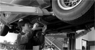
If all this time you’ve been wondering what these damn things do, here is a picture of my exhaust headers installed on my engine.

Here is how the shield will look when it’s installed. The scalloped parts of the shield is for the spark plugs, and associated wires. The indentations were made much like folding over the single sheet aluminum, but it is only bent to the profile needed to clear the spark plug boots. The curve of the shield is made simply by bending it over a large pipe, test fitting the contour to the headers. There three mounting points that need to be drilled, but I will be doing this another time because my day was done!
I thought he second one would take less time than the first one, but I was wrong. Patience, and care really need to be taken to make these pieces right, and rushing it only makes a bad product.
Previous Restoration Day
Next Restoration Day
Ferrari Home Page
www.tomyang.net
Blog
Forum

Resource