Fuses, and Y-Pipe Final Welding
1/25/02
Fuses, and Y-Pipe Final Welding!
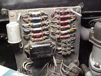
I installed all new fuses in the fuse panel today, but I realized that there isn’t any information in the GTE owner’s manual which tells which amperage fuse to use in each circuit! I decided to take an educated guess. The white fuses are 15 amps, the blue ones 25, and the red ones 16 amps. I figured the starter circuit should have a 25 amp, along with the cigar lighter/ horn circuit, but since each head light has its own circuit, a 16 amp should suffice. I continued on this logic until all the spaces were filled, but now I’m going to ask the owners of original GTEs with sorted out fuses (no aluminum foil fixes please!) to tell me what they have. If you can snap a picture, that would be even better. Eventually we’ll have a good idea what’s safe. It’s kind of funny how Ferraris have a pretty good fuse box, when my Sunbeam Alpine (Lucas Electrics) had two for the whole car, unless you count ALL the wiring as one big fusible link!
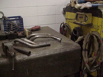
Now for the exciting news, I took my y-pipes down for final welding!
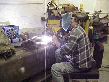
You may remember when I got my muffler hangers moved and John did the welding for me. He agreed to help me out again, and TIG weld the Y-pipes together, now that I have them tack welded into the exact positions to fit my car.
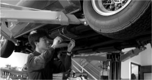
To quickly explain TIG (Tungsten Inert Gas) welding, the holder you see here, holds a tungsten wire, that is fed DC current. The pipes are clamped, or in this case, grounded to the welder through the steel table. As John steps on a foot pedal, inert gas flows out through the tip of the holder surrounding the tungsten wire. As John completes the electrical circuit by touching the tip to the piece being welded, an arc (basically an electrical short circuit) heats up the tip hot enough to melt the surrounding steel.

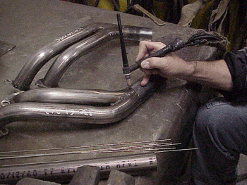
With his other hand, a wire (made up of the same material that’s being welded) is fed into the molten metal to fill the voids. The inert gas that’s surrounding this arc keeps the molten metal from oxidizing too quickly keeping impurities (which makes metal weak) out of the final weld.
The final product is nice even penetration where both pieces are heated evenly, and a nice bead of filler rod is added to strengthen what melted. The shielding gas leaves very little impurities, and gives a nice strong weld. For a guy whose nickname is “Junkyard Johnny” he does pretty nice work!
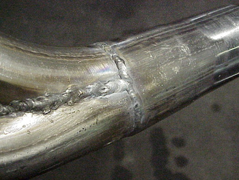
You can almost see the difference in the welding technique where the welds on the left of this pipe were done on a MIG, and the weld on the right is TIG. MIG is also a type of shielded gas welding, but the wire is fed into the weld through the handle, and is actually creating the arc. This makes for a short duration weld that quickly heats the surrounding area, and fills it with molten wire. Without getting into metallurgy, and physics, TIG is a better weld. MIG is good. TIG is better. I guess the best analogy would be, epoxy glue is pretty good stuff, but sometimes Elmers white glue will work fine! Know when to use which.
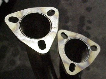
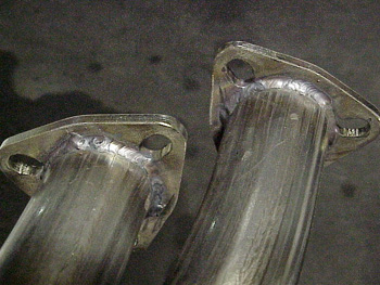
John did not weld the other side of the pipe at the flanges. His logic was that welding here risks warping the flange, and it’s more important to have a good flat surface to mate to the exhaust headers. He did suggest taking a ball peen hammer, and work the edges of the pipe into the flanges for nice smooth flow. I’ll also take a die grinder and carefully remove any rough spots, but that’ll have to wait until next week! Thanks a ton John!!!
Blog
Forum

Resource