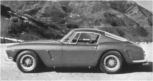
250GTE Engine Teardown
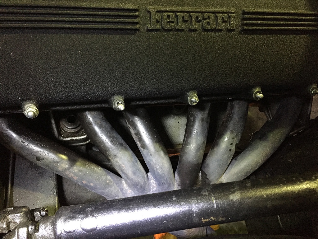
I continued working on getting a 250 engine out of the GTE by disconnecting the exhaust on the car. The early GTEs had a one piece header that is a lot harder to remove than the later two piece header. The one piece header pipes offer very little room to work, and the bends in the pipes obstruct access to the nuts with a wrench. I used every combination of wrench, socket, and crow’s foot wrench to get the nuts off.
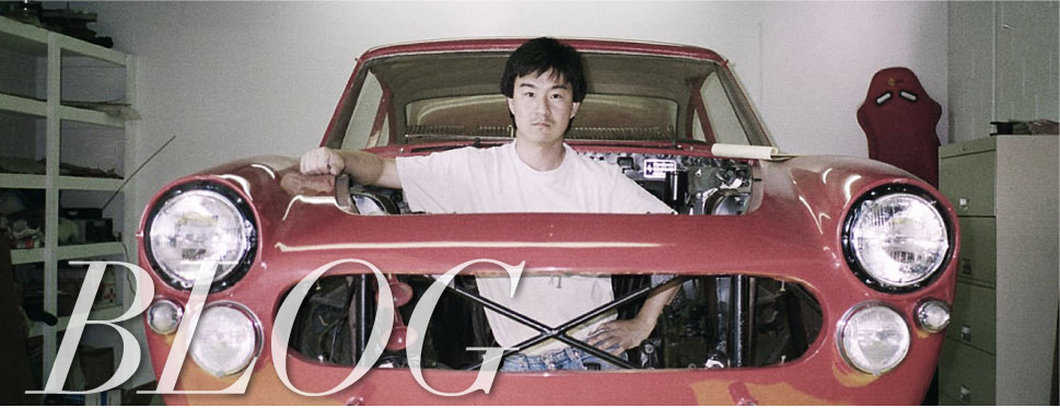
With everything finally disconnected, I pulled the engine out of the car.
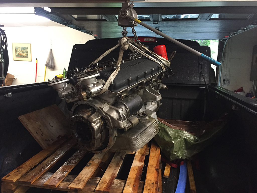
I loaded up my truck and brought the engine down to Francois’ shop to begin the dis-assembly, but before any work was done, I power washed some of the dirt and grease off the engine.
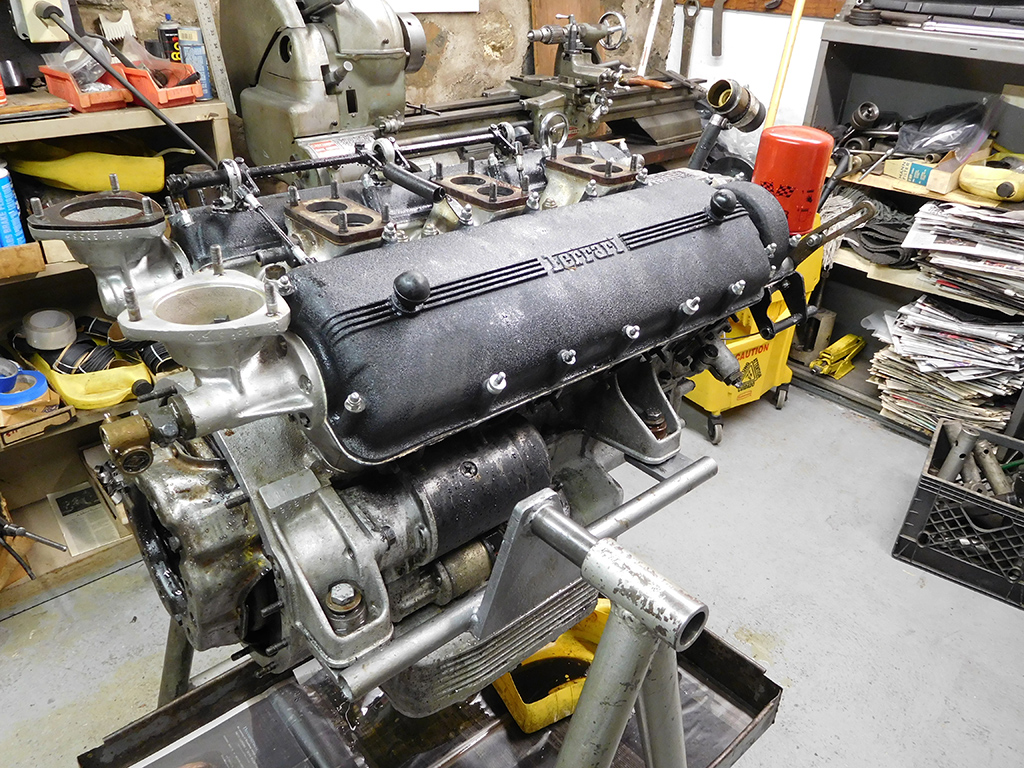
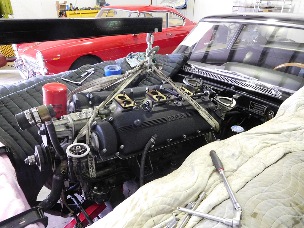
With the engine mounted on the engine stand, I could start the process of the tear down.
I try my best to notice little details on the engine to try and piece together the story behind the car. How things are assembled can tell me if the last person who worked on this engine knew what they were doing. The first mistake I spotted was a valve cover gasket wasn’t trimmed properly.
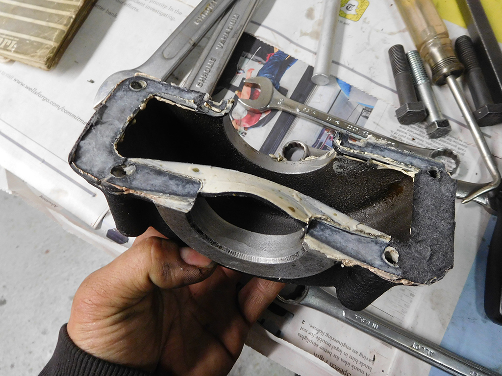
The center section of this gasket is supposed to be trimmed off so it doesn’t interfere with the end cap, but the last mechanic who installed this forgot to do it so it’s all buckled and distorted. If he hadn’t buttered up the gasket with so much silicone sealant, it would have leaked oil.
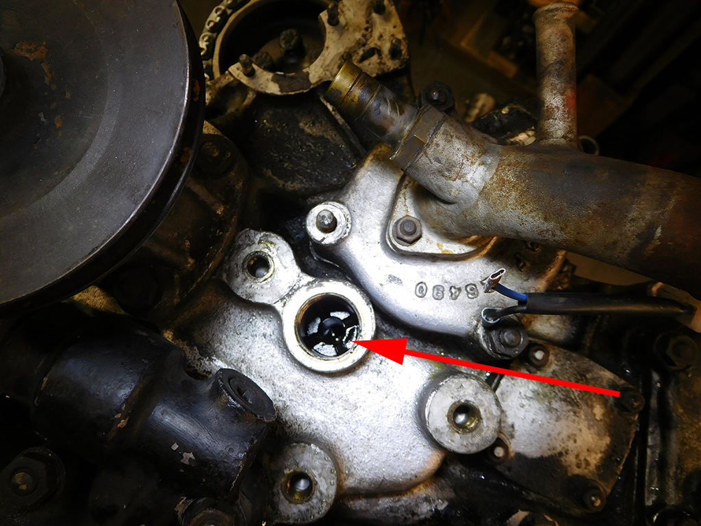
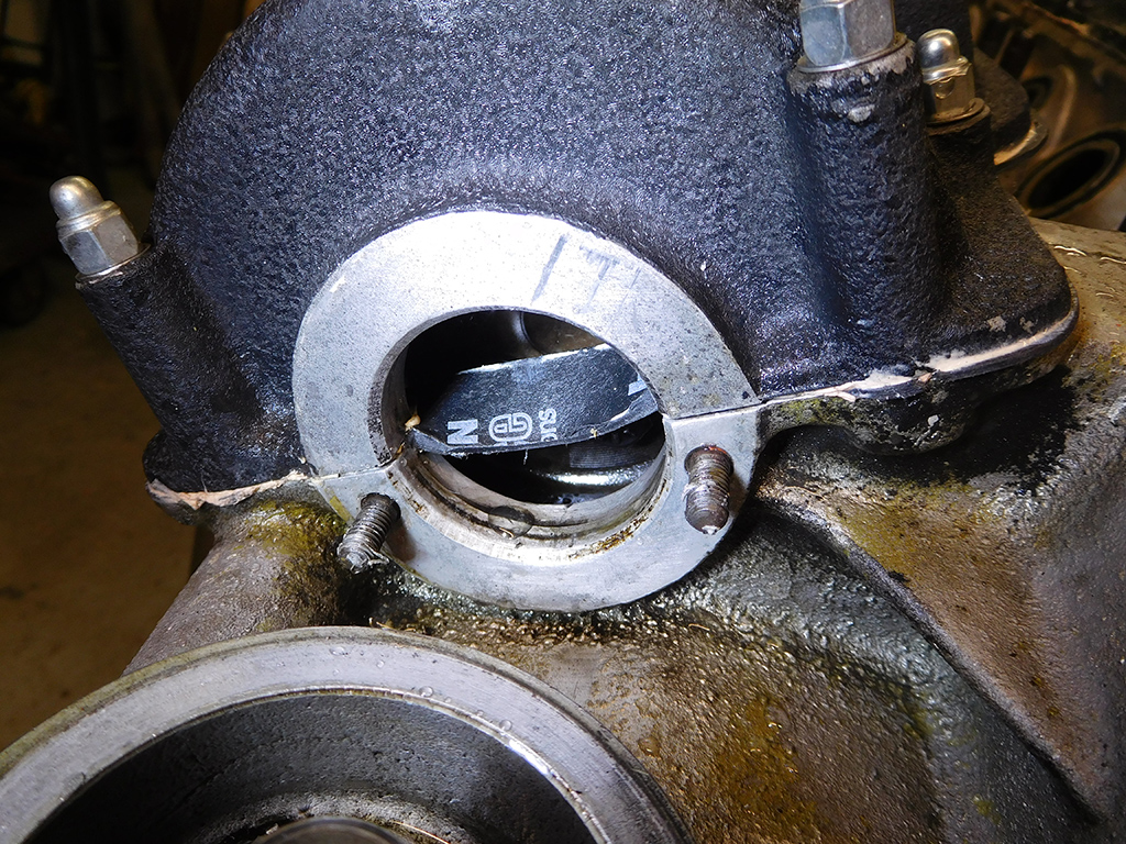
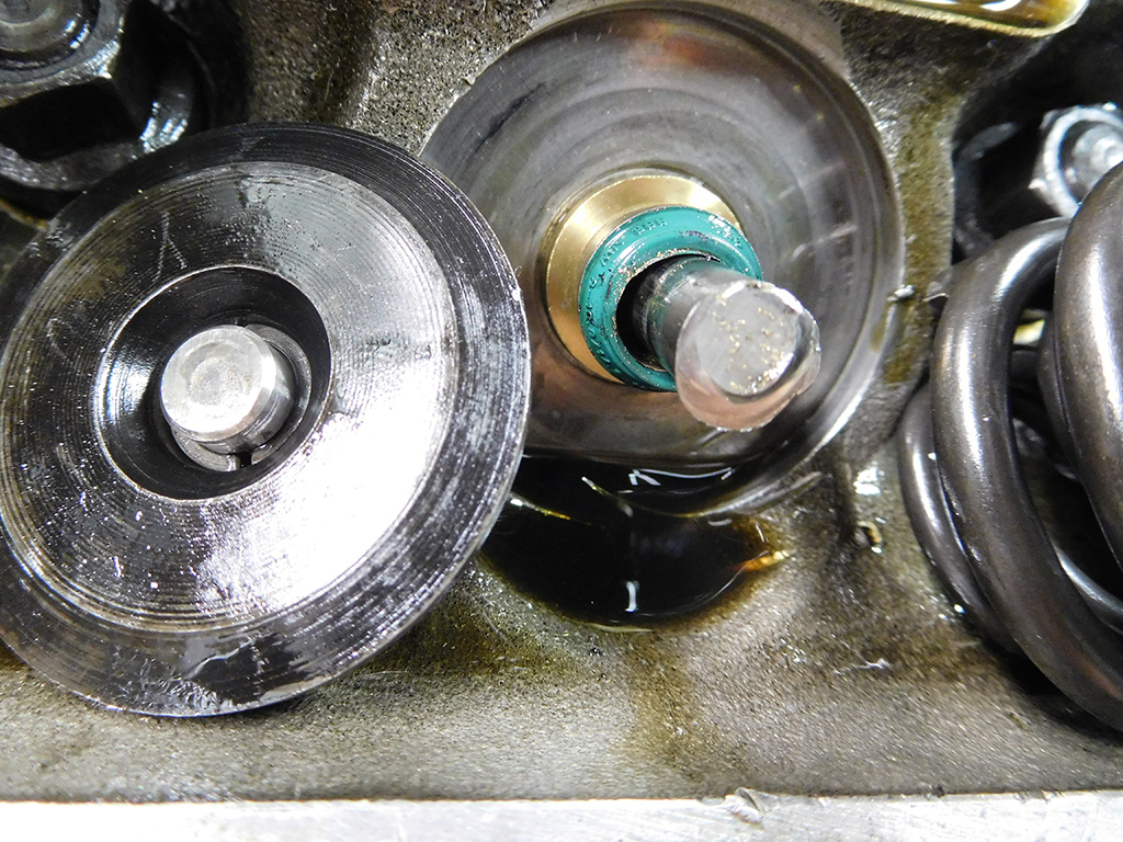
With the valve covers removed, I turned my attention to removing the timing chain chest. On 250s there is a hidden bolt that is removed with a special tool. If you don’t know about this bolt, you can pound and pry away at the timing chest and it will not come away from the block. I heard stories of people cracking the case of the timing chest, not knowing about this bolt.
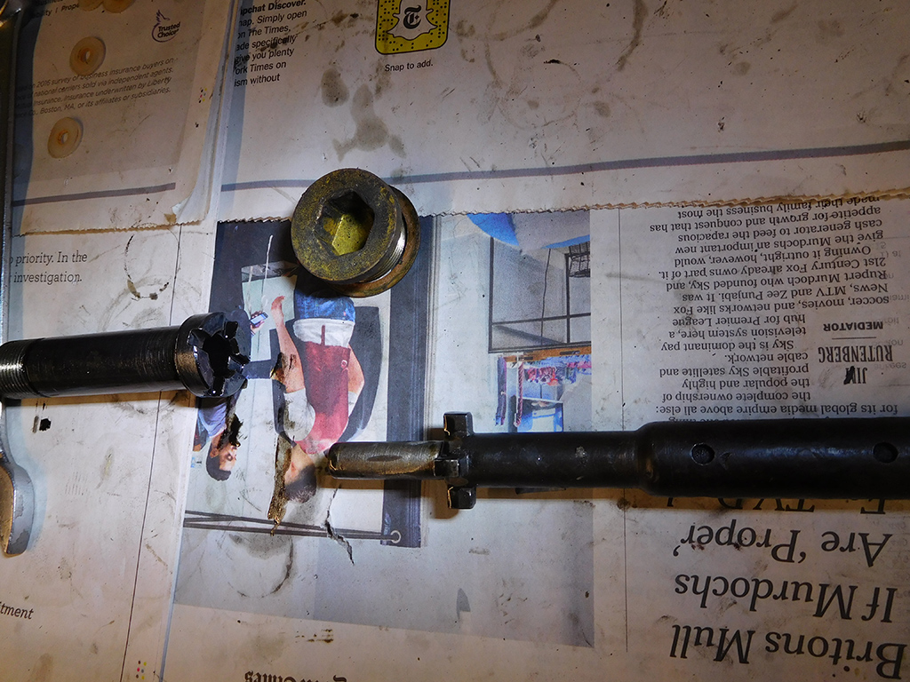
Here’s a picture of the bolt, and the special tool, along with the innocuous brass plug that could be mistaken for freeze plug.
I removed the timing chest and put it aside for dis-assembly later. I wanted to start on the heads to explore what happened to this engine.
When I removed the rockers, I found lash caps installed on the 1/6 bank, but none were installed on the 7/12 bank?! Lash caps are a common repair when there is excessive wear on the valve stem. It’s a stop gap measure to temporarily avoid pulling the heads and replacing the valves. There was definitely wear on the valve stems, but why did only one side of the engine have lash caps?
When I removed the rocker on #9 cylinder, I found the reason for no compression and the source of the clicking noise. The valve stem sheared off and the loose valve was bouncing between the piston and the head! If this had happened when the engine was turning at any high rate of speed, a lot more damage would have occurred. I’m really happy they never revved this engine higher than idle when the clicking first started.
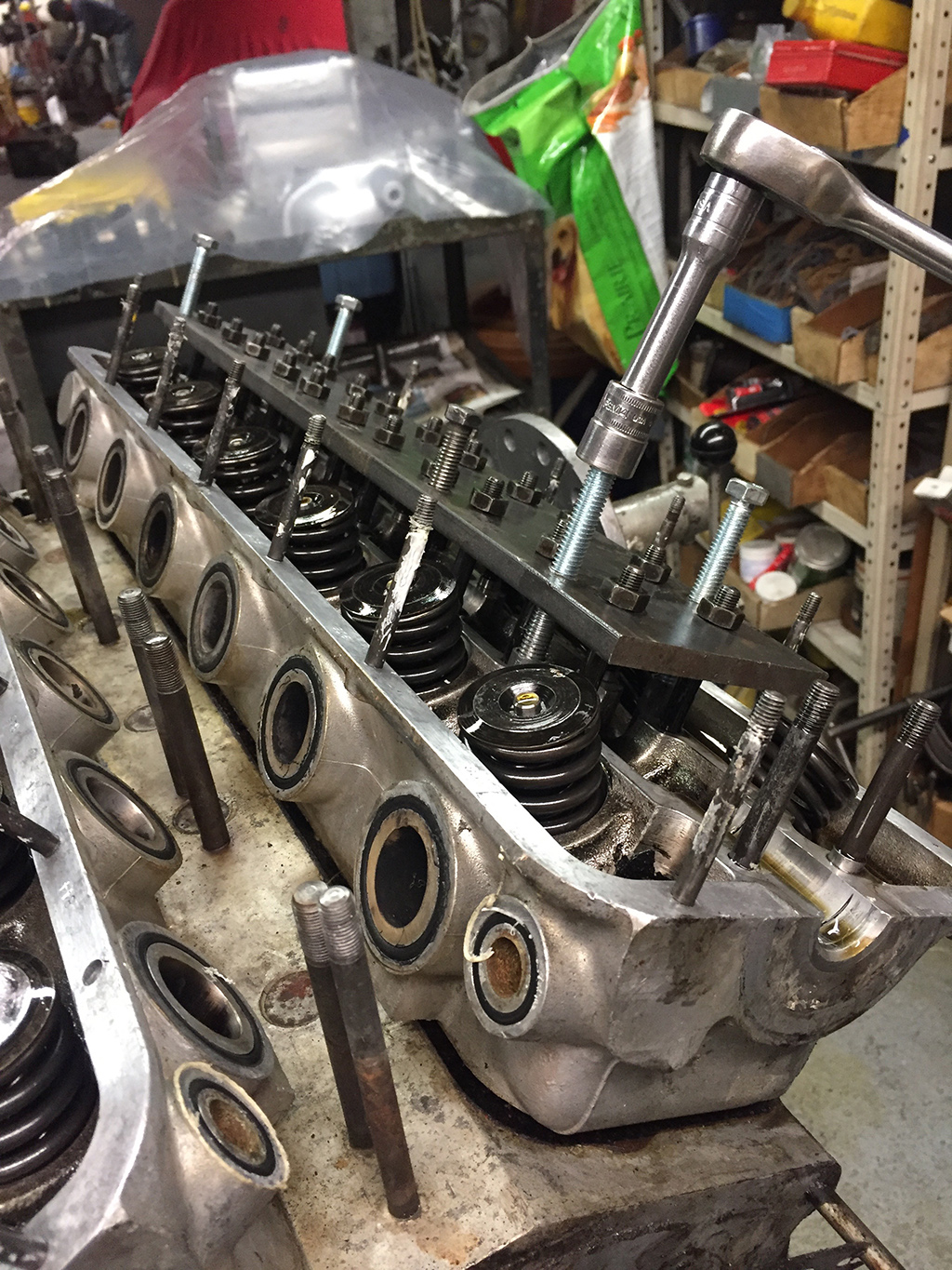
I mounted my head puller and started the process of pulling the heads. The head released without much resistance, because they have been off before. I would have expected a much harder battle if this was the first time pulling the heads.
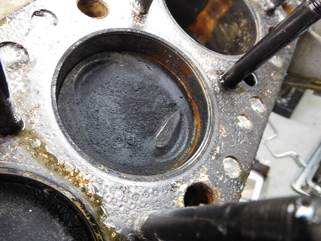
Cylinder #9 showed some marking on the piston crown, but the damage wasn’t too bad. I’ll continue assessing the rest of the engine before we decide how far the work will go.
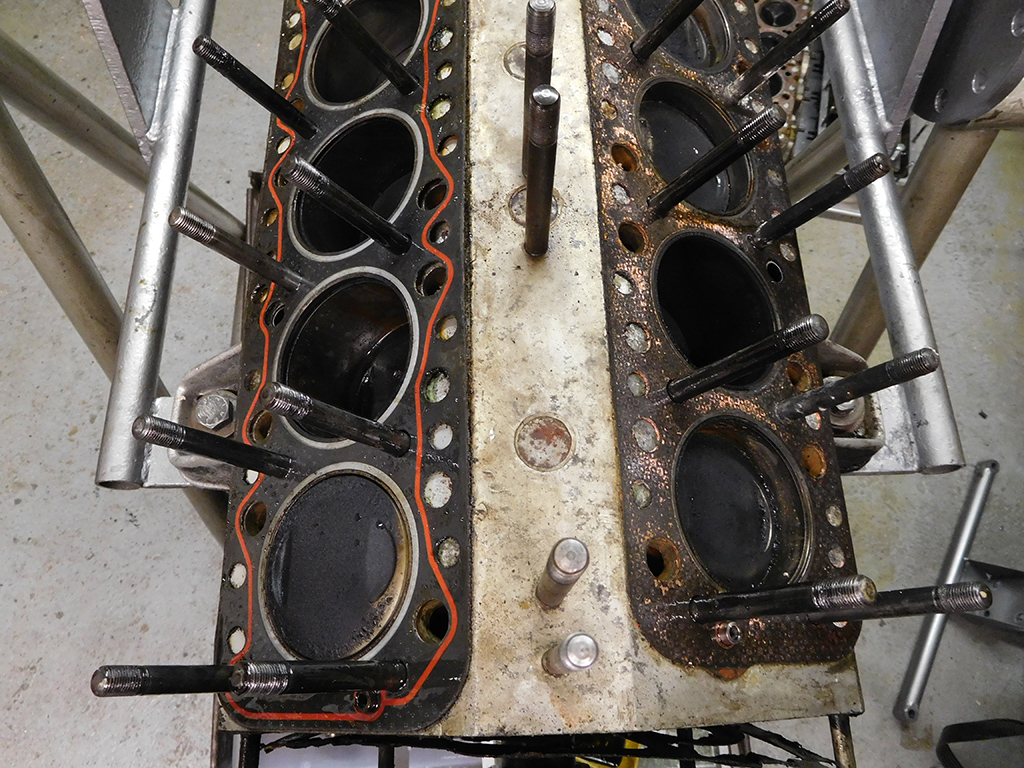
There are a lot of clues that point towards a sordid past on this engine. The clues point toward both heads being off this engine once before, but there were two different head gaskets! I suspect, one head may have been off twice. The reason being, this engine has newer valve guides installed in both heads but the different gaskets probably means they were done at separate times. I think something went wrong on one of the heads, and had to come off again. A different shop, or supplier, sold a different head gasket when the one head was removed.
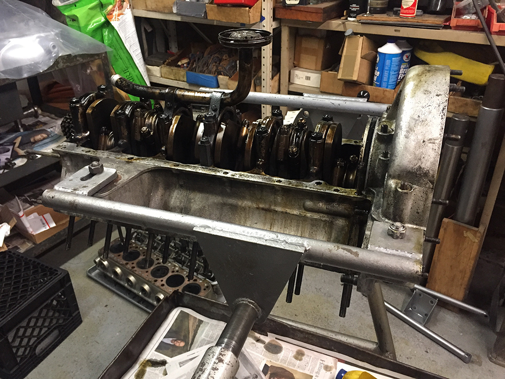
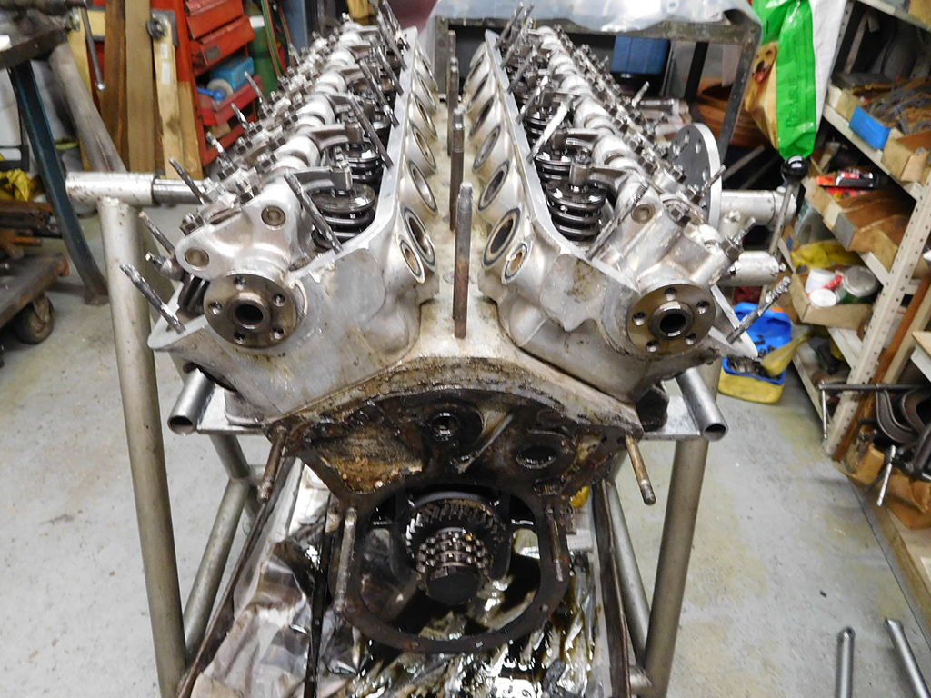
With the heads off, I turned the engine over to look closer at the bottom half of the engine. From all the dirt in the sump, I suspect the bottom end may not have been completely taken apart.
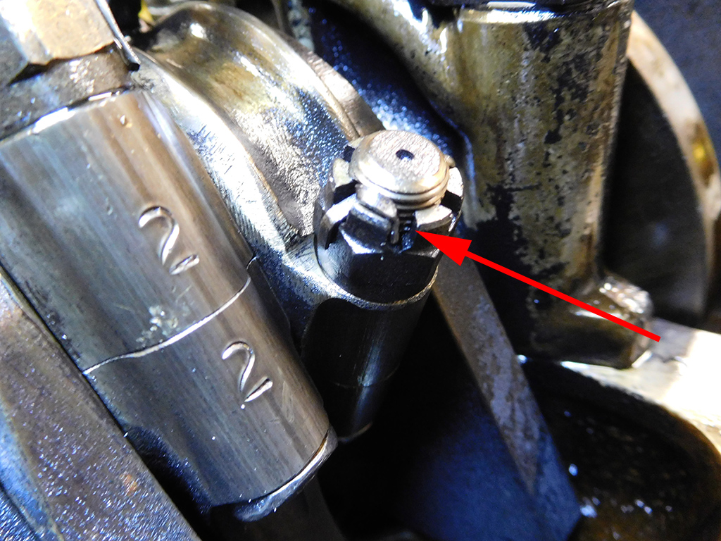
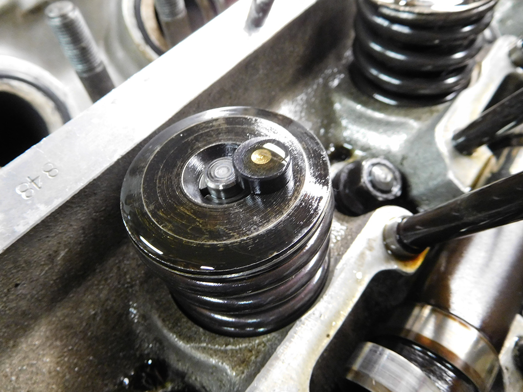
I looked very closely at the way the cotter pins were installed on the rod bolts. Ferrari had a very specific way of dressing the cotter pins. Francois explained that the Factory trained their engine builders to wrap one leg of the cotter pin over to the adjacent slot of the castle nut. Not everyone did it all the time at the factory, but this one was definitely done in that style.
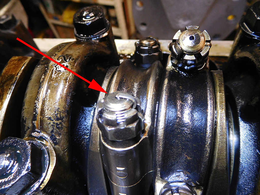
On another rod bolt, I found cotter pins done in the more common technique. What’s interesting was all the pistons from 1-6 were done in one manner and 7-12 were done in the Ferrari way. I would imagine if one person were building this engine, they would have installed all the cotter pins in the same manner, so it leads me to believe 1-6 pistons were removed from this engine at one time. Another clue was the 7-12 rods and all the main bearing caps were dirty and the 1-6 rods were much cleaner. The investigation continues…
Blog
Forum
Resource