Is the center section of the bell head salvageable? If so my first choice would be to find a fitting with the right internal threads (if possible). Then I would turn the OD down in a small lathe to match the existing pipe, leaving a small step that fits in the center section. I would then lathe cut some stock to match the existing hose end leaving a step on it too. Next I would cut off the hose end and fit both pieces on either side of the center section. To join it I would braze the new fittings in place and file the braze to hide the joint. If a small lathe is not available it will be a lot more time consuming. But the hose end can be formed out of exhaust tubing and the other piece could be ground down with the drill, a bench grinder, and a steady hand. Clearly the lathe would result in a more professional looking repair, but if you do a lot of hand finishing and paint it with wrinkle paint both repairs should be invisible when you are done. Let me know if you need a hand.
Hi Jim, the only part I have that is original is the tail section where the bronz plug goes. The bell shaped head is gone. Yes, I do have a bench lathe. But, are you saying to use a cast steel bell reducer that you might get from a plumbing supply store like this and then cut off the excess casting on the lathe?
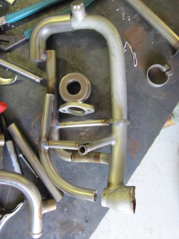
Sorry I thought you were trying to repair the tube shown in the second photo. I thought the bell section (I called it the center section) was still good. Do you have some photos of the one you are trying to repair?
The fitting you suggested does have some potential. Those curves are not that easy to copy on a lathe, especially on the inside. But it could be done.
The gears are tuning, let me think about it some more. Some photos of it may spark some ideas.
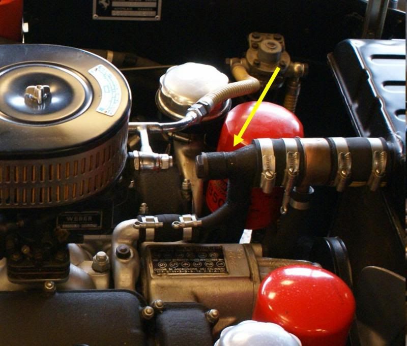
Hi Jim, about 10 years ago I decapitated my manifold because it was like Swiss cheese and replaced it with a copper T. From the neck down it is still the original tube and in pretty good shape. Now, I want to replace that copper T with something closer looking to the original. The only thing that I saved from the old head is the threaded tail and the bronze plug. Thanks.
That makes it a lot tougher. Some ideas rolling around in my head involve metal spinning, lathe cutting it from the fitting you suggested, lathe cutting it from solid bar stock, and hydro forming it. Unfortunately all of them would take a tremendous amount of time and effort and in some case equipment and all of them would most likely take some trial and error to get a proper looking part. Once you take all of that into account, the one Greg offered starts to look like the lowest cost option. I will keep thinking about it, right now it looks like buying one is the best option. My second choice would be to have a go at cutting one on the lathe, but I think that would be very time consuming. At least it would be on the equipment I have.
Ok, some more ideas. What if we made it in four parts.The threaded boss you already have. Braze it to a short straight pipe cut to length the same size as the boss. Then fabricate a sheet metal cone out of a flat piece of sheet metal. Based on the diameters and angles it is simple geometry to come up with a pattern. Roll it into a cone that matches the small and large pipe sizes. Then use a short piece of straight pipe cut to length to match the hose end of the pipe. Weld the whole assembly together. File and hammer the welds to soften the bends a little to match the original. Fill any dents or issues with JB Weld and sand to shape. If you are good at working sheet metal this method will work with some pretty basic tools. FYI I would put the weld seam on the cone where the other pipe tees in so it is hidden and most of it is cut away where the tee intersects it. An alternative to steel, you can use copper and silver solder it. With the copper you can aneal it and do a lot more hammer work on it (if you need to).
John,
I would have the bell reducer made by a machine shop out of 300-series stainless steel. It would not be a difficult job for a competent shop. The tubes would also be 300-series stainless bent by a custom exhaust shop or competent plumber; if they couldn’t do an honest bead on the end, a small flare would do. Welding would be by TIG. Then beadblast and finish with a crinkle paint, if that’s correct. A proper-looking job and the durability of stainless. Make half-a-dozen and sell the rest to cover the cost.
You must have huge trust in anti-corrosive detergents in cooling liquids to even think of mixing stainless with an aluminum castings that cost an arm and a leg. As I've said before, when you put stainless into a wet system, you never know what's going to happen. Best wishes, Kare
Kare,
That’s interesting. Would the stainless “push” the corrosion site more to the aluminum block and heads since aluminum is higher on the activity scale than iron, even though the iron is passivated by the chromium in the stainless alloy? Did John’s original bell reducer corrode as an unintentional sacrificial anode? Perhaps the uncertainty of using stainless in a cooling system comes from whether the metal tubing parts are in electrical contact with the block or not, thus completing an electrical circuit. Being electrically isolated from the engine, I would think that the only effect would be chemical corrosion which should be of nearly no effect on stainless parts and would remain high on the aluminum parts due to aluminum being high on the activity scale. Chlorine ions commonly found in water cause pitting in both aluminum and stainless steel, although the rate or corrosion due to the chlorine ions is likely much higher in aluminum than stainless steel. Chemical corrosion should be reduced by changing the coolant frequently (not often done in practice) or using an inhibitor or both. Do one of the alloying components of stainless steel cause the problem? Perhaps the problem is coincidental (and anecdotal?) and unrelated to the use of stainless steel. I am having difficulty understanding how a component that is relatively chemically inert could have a significant impact in this chemical-electrical corrosion process.
In any case, I believe my fabrication scheme will yield the best parts. If you are correct, perhaps a different choice of metal is in order (copper or brass?). John could use zinc or magnesium to sacrifice themselves in preference to the block and heads. Better keep one of those extra assemblies, John, just in case the first one gets eaten up.
As a rule, the worst corrosion occurs at a point where water and air meet-- the more the oxygen the better the oxidation, right? So the constantly submerged parts corrode later than the parts that are semi-submerged. This is why the head of most of these manifolds rot away first. The same goes for the tube system that connects this manifold to the back of the cylinder heads--the front part rots first because this part is semi-empty then the car is parked.
John Vardanian wrote:
If I were to go with mild steel, would welding the seams from the inside be feasible?
john
It may be possible on the cone, it will depend on the equipment you are using. I would be surprised if you could weld the cone to the tube on the inside with the equipment I have / I have seen. Personally I do not think it matters. If you have a good weld penetration you can file/grind the excess weld off pretty quickly. JB weld works as a nice filler if there are any depressions that need to be filled. Use the JB weld just like bondo, it will hold up to the temperatures seen by the tube.
If you are trying to get a rounded shoulder on the large end of the cone you can turn a wooden form on the lathe in the shape you need and hammer form the rounded shoulder. An understanding of shinking sheet metal is need to accomplish that.
Thanks Jim, I am thinking about weldable sheet metal for the lampshade and exhaust pipes for the two cylinders at either end, as well as a third pipe for the neck. I would need to make a cardboard template first for the lampshade and incorporate into it the hole for the neck. Would brazing work better than mig welding here? Thanks.